







The most expensive cable in a mining farm is usually the one that has to be replaced after commissioning.
A cable may look adequate on a quotation and still overheat when hundreds of ASIC miners run continuously. A transformer may have enough nameplate capacity and still suffer from high ambient temperature, altitude, harmonics, poor power factor, or insufficient expansion margin. A PDU may provide enough outlets while lacking the current capacity required to power them safely.
That is why mining farm power distribution must be designed from the actual operating load backward.
The correct sequence is:
ASIC load → facility load → transformer → switchgear → container feeder → PDU → individual miners
Start with usable kilowatts. Everything else follows.
Calculate Continuous Load Before Selecting Equipment
ASIC miners operate 24 hours a day. Their electrical system must therefore be planned as a continuous-load installation rather than a short-duration industrial process.
The basic IT load calculation is:
IT Load = Miner Quantity × Single-Miner Power
The facility load includes cooling and auxiliary systems:
Facility Load = IT Load × PUE
For example, a mining farm with 1,000kW of ASIC load and a planning PUE of 1.05 requires approximately:
1,000kW × 1.05 = 1,050kW
That extra 50kW may include container fans, pumps, controls, network equipment, lighting and other auxiliary systems.
Local electrical codes may require additional continuous-load capacity. In the United States, many continuous-load conductor and overcurrent-protection calculations apply a 125% factor under relevant NEC conditions. Other countries follow IEC standards or local regulations.
Do not add percentages blindly. Ask a licensed electrical engineer to determine which margins and derating factors apply at the project location.
Three-Phase Current Calculation
For a three-phase AC system:
Current = Power ÷ (√3 × Voltage × Power Factor)
Assuming a 1,050kW facility load and a power factor of 0.95:
| System Voltage | Approximate Current |
|---|---|
| 400V | 1,596A |
| 415V | 1,538A |
| 480V | 1,330A |
The same mining load requires considerably less current at 480V than at 400V. Lower current can reduce cable size, parallel conductor quantity, voltage drop and distribution losses, although equipment compatibility and local utility standards must also be considered.
Pro Tip: Never request a transformer or mining container quotation using only “1MW” as the project requirement. Specify whether 1MW means utility capacity, facility load or ASIC IT load.
Transformer Sizing: Kilowatts Are Not kVA
Mining operators usually think in kilowatts. Transformers are normally rated in kilovolt-amperes.
The preliminary relationship is:
Transformer kVA = Facility Load kW ÷ Power Factor
For the previous 1,050kW example:
1,050kW ÷ 0.95 = 1,105kVA
This does not mean that a 1,125kVA transformer is automatically the correct final selection. The engineer must still evaluate:
Continuous-load requirements
Utility voltage and frequency
Ambient temperature
Site altitude
Transformer efficiency
Harmonic loading
Future miner upgrades
Cooling-system startup loads
Required redundancy
Local code and certification
Available standard transformer ratings
After these factors are considered, a designer may evaluate a 1.25MVA or 1.5MVA transformer class for a nominal 1MW mining block. That is an engineering decision, not a universal product rule.
One Large Transformer or Several Modular Transformers?
A 5MW mining farm with a 1.05 PUE has an estimated facility load of 5.25MW. At a 0.95 power factor, the preliminary apparent-power requirement is approximately:
5,250kW ÷ 0.95 = 5,526kVA
A single 6.3MVA transformer may appear efficient on paper. Several smaller transformer blocks may provide better deployment flexibility.
| Architecture | Advantages | Risks |
| One centralized transformer | Fewer major components and a simpler one-line diagram | Large failure domain and longer low-voltage cable runs |
| Multiple modular transformers | Easier phased deployment, shorter feeders and smaller failure zones | More switchgear, protection and site coordination |
| Redundant transformer design | Higher availability and easier maintenance | Higher CAPEX and more complex control logic |
Schneider Electric’s IEC-based Electrical Installation Guide recommends considering total power, scalability, load sensitivity, harmonics, replacement logistics and redundancy when deciding the number of MV/LV transformers.
For a 3MW to 5MW modular mining farm, dividing the site into repeatable electrical blocks is often easier to expand and maintain. If one block is shut down, the remaining containers can continue operating.
Pro Tip: Redundancy must be defined precisely. Two transformers sharing the full load are not automatically redundant. If either transformer cannot carry the required emergency load after the other fails, the design only divides the load.
The Recommended Mining Farm Power Path
A typical containerized mining farm uses the following power architecture:
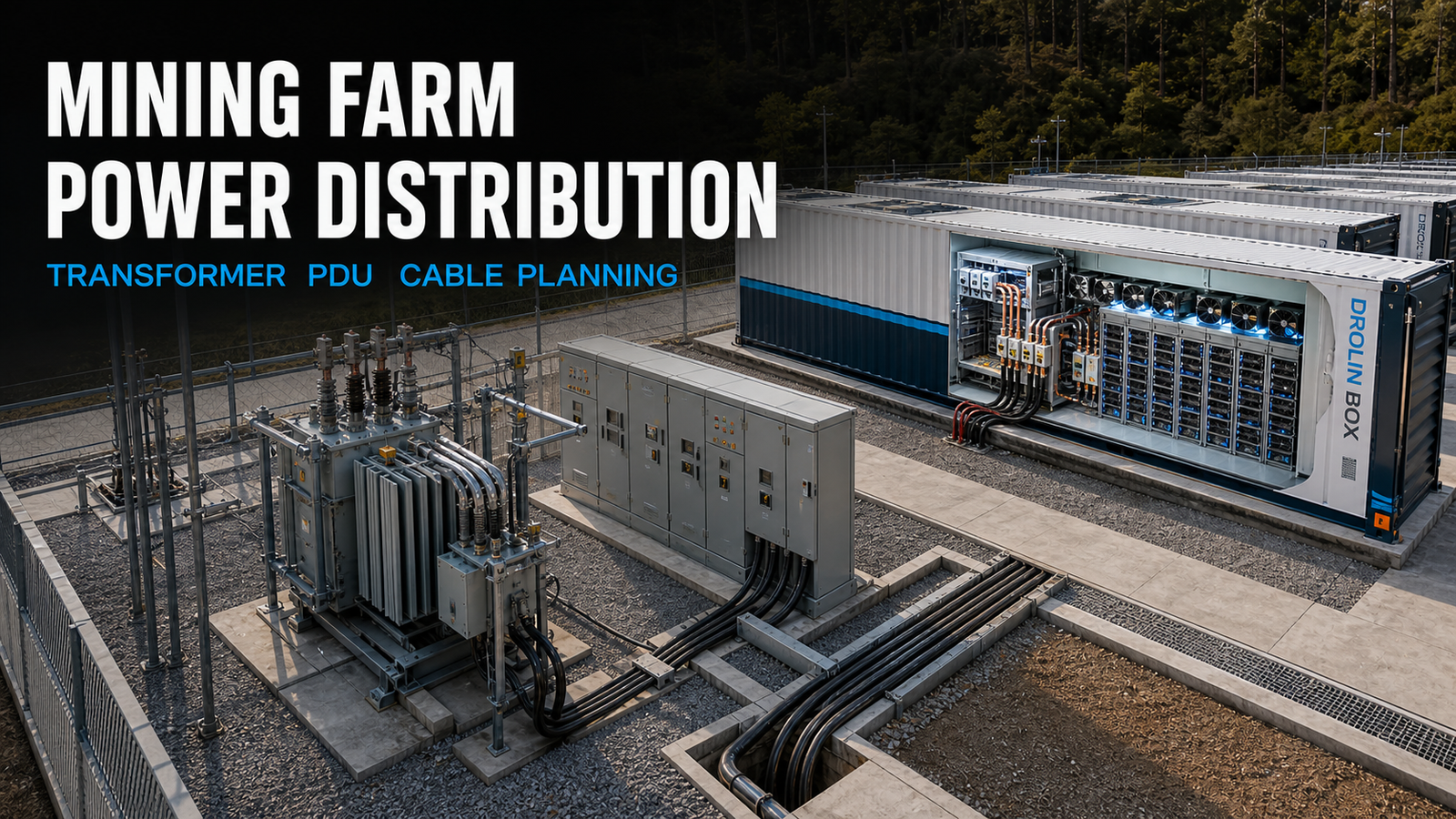
Utility or Substation → MV Switchgear → Transformer → Main LV Switchboard → Container Feeder → Main Container Cabinet → PDU → ASIC Miners
Cooling equipment should also be identified clearly. Fans, CDU pumps, dry coolers and control systems may be connected through dedicated auxiliary feeders so that their protection and monitoring are not mixed with the ASIC branches.
Each electrical block should include:
Main disconnect
Overcurrent protection
Short-circuit protection
Surge protection
Grounding and bonding
Energy metering
Phase-current monitoring
Emergency shutdown logic
Temperature and alarm monitoring
Lockout and maintenance isolation
The breaker interrupting rating must exceed the available short-circuit current at its installation point. This value depends on transformer rating, transformer impedance, cable impedance and upstream grid conditions.
A larger transformer can increase available fault current. Upgrading transformer capacity without recalculating switchgear ratings can create a serious protection problem.
Choosing a PDU for a Mining Farm
A PDU for a mining farm is not simply a power strip with more outlets.
In container projects, the term may refer to an industrial branch distribution unit, rack-level distribution assembly or container-mounted PDU that divides a large incoming feeder into protected circuits for groups of ASIC miners.
The PDU should be selected according to:
Rated input voltage
Three-phase configuration
Total current rating
Branch-circuit current
Breaker quantity and rating
Outlet or connector type
Miner PSU plug type
Number of miners per branch
Continuous-load allowance
Phase-balancing strategy
Temperature rating
Dust and moisture protection
Local certification
Metering and communication protocol
Outlet quantity is not usable capacity. A PDU with 30 available connections cannot safely power 30 miners unless its incoming feeder, busbar, breakers, connectors and continuous-current rating support the combined load.
Phase Balancing Matters
When single-phase miner power supplies are distributed across a three-phase system, the miners should be allocated across phases A, B and C as evenly as practical.
Poor phase balance can cause:
Uneven conductor heating
Reduced transformer utilization
Higher neutral current
Nuisance breaker trips
Voltage imbalance
Difficult capacity forecasting
A monitored PDU should report voltage, current, power and energy at the main or branch level. Remote monitoring helps operators identify overloaded branches, missing miners and abnormal phase conditions before a trip occurs.
Vertiv’s power-distribution portfolio separates rack PDUs from switching and distribution cabinets, which reflects an important project distinction: the equipment distributing power to a container is not necessarily the same equipment distributing power inside a rack or miner row.
DroLin Box Reference Configuration
The DroLin Box 40HC integrated liquid-cooling mining container has a reference configuration for up to 192 S19/S21 Hydro-class miners, approximately 1,300kW of heat-transfer capacity at 25°C ambient temperature, a 2500A distribution cabinet and 12 × 175A PDUs.
These are reference specifications. The final cabinet, PDU and branch configuration must be adjusted according to miner power, project voltage, firmware mode, local code and the required operating reserve.
Pro Tip: Send the supplier the miner data-sheet power and your intended firmware mode. Designing a PDU around standard mode and later running miners in a high-power mode can overload branches without increasing the miner count.
Cable Planning: Ampacity Is Only the First Check
Cable selection cannot be based on current alone.
The engineer must evaluate:
Copper or aluminum conductor
Conductor cross-sectional area
Insulation temperature rating
Ambient temperature
Underground, tray or open-air installation
Number of grouped conductors
Cable length
Parallel cable arrangement
Termination temperature rating
Voltage drop
Short-circuit withstand
Grounding conductor size
Local fire and environmental requirements
Schneider Electric’s Electrical Installation Guide identifies cable sizing as a factor that directly affects overcurrent protection, voltage drop and prospective short-circuit current.
Keep Low-Voltage Cable Runs Short
At megawatt scale, long low-voltage feeders become expensive and inefficient.
A practical site layout places transformers and main switchboards close to their assigned container blocks. Medium-voltage power can be distributed across the site before being stepped down near the load.
This strategy may reduce:
Copper or aluminum conductor quantity
Parallel feeder count
Voltage drop
Cable-trench congestion
Electrical losses
Installation labor
The correct architecture depends on local MV equipment cost, utility requirements and the number of mining containers.
Voltage Drop Is an OPEX Issue
Maximum voltage-drop limits vary by country and electrical system. IEC-based guidance provides typical limits but also warns that excessive voltage drop represents continuous power loss and can create problems for voltage-sensitive loads.
Mining farms should usually target a tighter internal voltage drop than the maximum legal limit where economically practical.
A voltage-drop calculation should include:
Actual operating current
Cable resistance and reactance
Route length
Power factor
Conductor operating temperature
Parallel-conductor arrangement
Even 10kW of avoidable continuous distribution loss consumes:
10kW × 24 hours × 30 days = 7,200kWh per month
At USD 0.07/kWh, that equals:
7,200kWh × USD 0.07 = USD 504 per month
One inefficient feeder may look minor. Several inefficient feeders operating all year become a measurable OPEX problem.
Worked Example: A 1.3MW Container Feeder
Assume a container electrical load of 1,300kW and a power factor of 0.95.
| Voltage | Estimated Three-Phase Current |
| 400V | 1,975A |
| 415V | 1,904A |
| 480V | 1,646A |
This calculation explains why the project voltage must be confirmed before the cabinet and cable schedule is finalized.
At 400V, the project may require a higher-current switchboard and more parallel conductors. At 480V, current is lower, but every ASIC PSU, fan, pump, control transformer and protective component must be compatible with the selected voltage.
The transformer-to-container distance then determines whether the preliminary conductor arrangement still meets ampacity and voltage-drop requirements.
Do the electrical calculation before the factory cuts the cable openings.
Protection, Grounding and Monitoring
A reliable mining farm must be able to isolate a fault without shutting down an unnecessarily large part of the site.
The protection study should consider:
Transformer primary protection
Main LV breaker
Container feeder breaker
PDU branch breakers
Short-circuit coordination
Ground-fault protection
Surge protection devices
Earthing and equipotential bonding
Lightning protection
Emergency shutdown
Arc-flash risk and labeling
Phase loss and voltage imbalance
High-temperature alarms
Selective coordination is especially valuable in modular mining farms. A fault on one PDU branch should ideally trip that branch, rather than the main switchboard serving several containers.
Monitoring should be available at three levels:
Site level: Total demand, transformer loading and utility quality
Container level: Voltage, current, energy and auxiliary load
PDU level: Branch current, phase balance and overload alarms
Without container-level metering, operators cannot accurately compare performance between containers or locate electrical losses.
Information Required for a Mining Farm Power Proposal
Before requesting a transformer, PDU or mining container proposal, prepare the following information:
Project country and site location
Available continuous power in MW
Utility or transformer capacity in MVA
Supply voltage and frequency
Existing transformer and switchgear specifications
ASIC brand and exact model
Miner quantity
Standard or high-power firmware mode
Single-miner rated power
Air cooling or liquid cooling
Estimated PUE
Distance from transformer to each container
Ambient temperature and altitude
Underground or cable-tray installation
Required redundancy
Expansion target
Local certification requirements
Required commissioning schedule
These details allow the supplier to develop a preliminary one-line diagram, transformer arrangement, cabinet rating, PDU schedule and container feeder plan.
Final Decision Framework
A mining farm power-distribution system should answer five questions before equipment is ordered:
How much continuous IT and facility power will the site actually use?
What transformer architecture limits downtime and supports expansion?
Can every PDU branch support the connected miners continuously?
Do the cables meet ampacity, voltage-drop and fault-withstand requirements?
Can the operator monitor and isolate each electrical block?
The lowest-cost transformer or smallest cable does not automatically produce the lowest-cost mining farm.
Stable voltage, selective protection, manageable failure zones and measurable energy use protect the real investment: miner uptime.
DroLin Box provides modular air-cooled and liquid-cooled mining-container solutions with integrated distribution cabinets, PDUs, controls and cooling infrastructure.
To request a preliminary power-distribution proposal, submit your available continuous power, supply voltage, miner model, miner quantity, site location and transformer-to-container distance through the DroLin Box contact page.
Frequently Asked Questions
What size transformer is required for a 1MW mining farm?
Start with total facility load rather than miner load alone. If the IT load is 1MW, PUE is 1.05 and power factor is 0.95, the preliminary apparent-power requirement is approximately 1,105kVA. Continuous-load rules, temperature, altitude, harmonics and expansion margin must then be applied by the project engineer.
How many miners can one PDU support?
Divide the PDU’s allowable continuous branch capacity by the actual input power of each miner. Breaker rating, connector rating, voltage, phase allocation and local electrical rules must also be checked.
Is 480V better than 400V for a mining farm?
A 480V system carries less current for the same power, which can reduce conductor requirements and voltage drop. It is only suitable when the miners, cooling equipment, controls and local utility system are compatible.
Should each mining container have a separate transformer?
Not always. A transformer can serve one or several containers. The decision depends on container load, feeder distance, redundancy, expansion plans, maintenance strategy and available standard transformer sizes.