
Coolant Distribution Units (CDU) for ASIC Mining Farms: An Engineering-Grade Analysis
A pump seal failure in an air-cooled facility costs you thirty minutes of labor. The same failure in a liquid-cooled mining container — without a properly configured CDU — costs you something else entirely. It puts $3.2 million worth of ASIC hardware at uncontrolled temperatures within minutes. That is not a hypothetical. It is the design scenario every liquid cooling engineer solves before the first miner powers on.
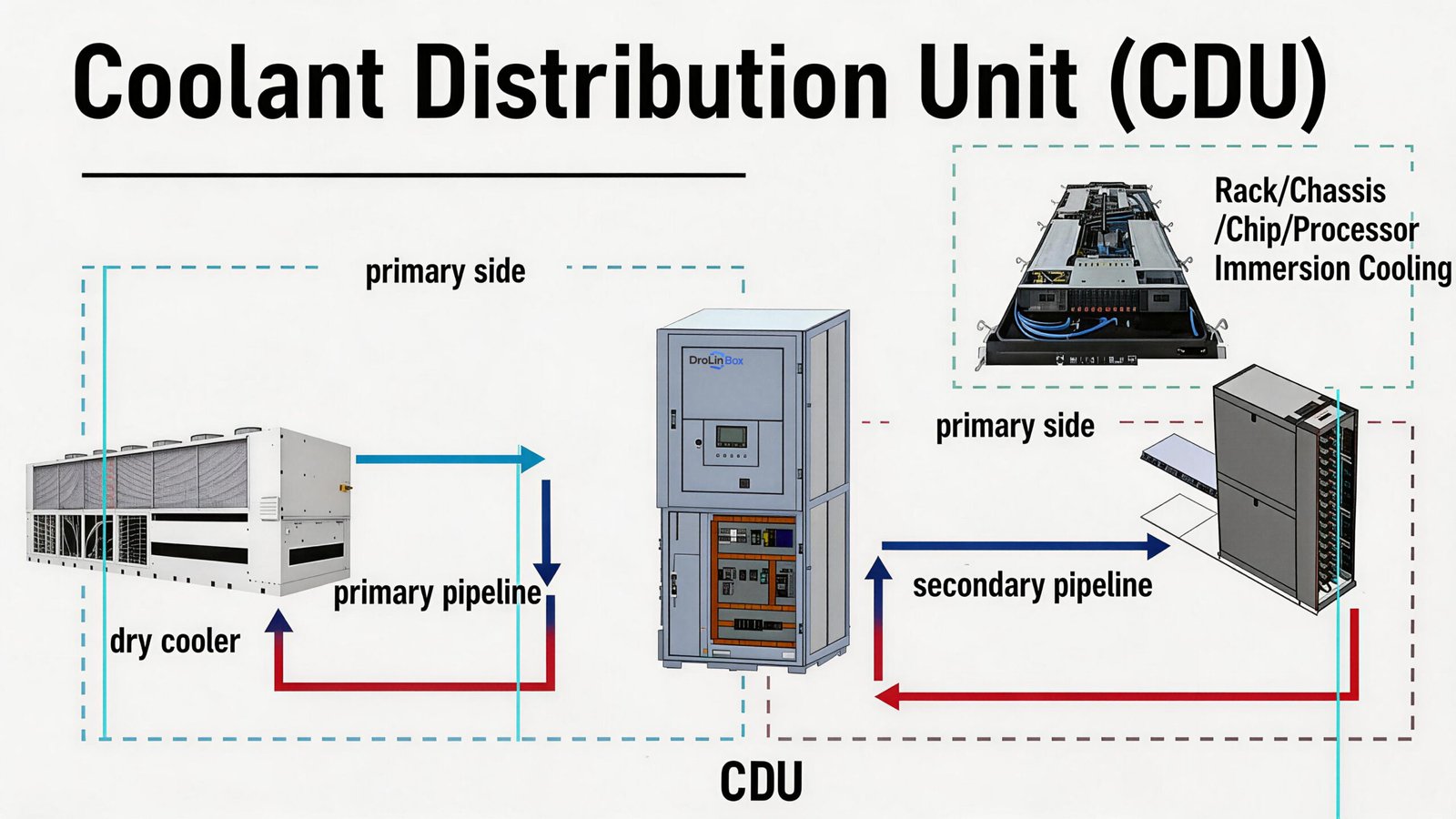
The Coolant Distribution Unit sits at the center of that problem. Far more than just a standalone pump, heat exchanger, or controller, a CDU integrates all three components into a single managed system. This system serves as the absolute physical barrier between your facility water and your high-value mining hardware. Consequently, understanding how it operates—and knowing how to select the right one—is what separates highly profitable farms from those suffering devastating cooling failures.
The Thermal Bottleneck Air Cooling Can No Longer Solve
The physics are straightforward. Air carries a volumetric heat capacity of approximately 1.2 kJ/m³·K. Water sits at 4,186 kJ/m³·K. That makes water roughly 3,500 times more effective at absorbing heat per unit volume.
In 2019, a farm running Antminer S17 units at 2,520W each could manage with forced-air cooling. It was inconvenient, but workable. In 2026, a 40HC container running 420 Antminer S21 Hydro units at 5,360W each cannot. Air cooling is no longer an engineering challenge at that scale — it is a physical impossibility.
The market confirms this shift. According to Dell’Oro Group, the Data Center Direct Liquid Cooling market surged 156% year-over-year in Q2 2025. By 2029, manufacturer revenue will reach $7 billion. The CDU segment alone — the category most relevant to ASIC mining operators — reached $2.54 billion in 2026. It grows at a 14.3% CAGR toward $7.38 billion by 2034. This is not a trend. Modern ASIC and GPU hardware has structurally outgrown air-based heat rejection.
When operators switch from air to liquid cooling, the CDU becomes unavoidable. Every liter of coolant that absorbs heat from an ASIC water block must pass through the CDU’s heat exchanger. The CDU transfers that heat to the facility loop. It then returns coolant at a controlled temperature — typically 35°C ±1°C — before the coolant re-enters the miners. Without a CDU, you do not have liquid cooling. You have uncontrolled water circulation with no temperature management, no pressure stability, and no loop isolation.
Redundancy Engineering: How Dual-Pump Architecture Eliminates Single Points of Failure
Most CDU marketing describes dual-pump systems in one sentence: “features redundant pumps for reliability.” That generic phrase tells a 1MW farm operator nothing. Real-world reliability hinges on the precise switch logic and failure detection thresholds. More importantly, it depends on whether the transition causes a pressure drop—because even a temporary interruption can trigger ASIC firmware protection shutdowns.
In a properly engineered N+1 dual-pump CDU, both pumps connect in parallel to the same inlet manifold and outlet manifold. Under normal operation, one pump carries 100% of the design flow rate. For a 1MW DroLin CDU, that means maintaining rated volumetric flow against total system pressure drop — across all cold plates, manifolds, and return lines. The standby pump holds pressure but does not spin. Its check valve stays closed to block backflow.
The CDU detects failure through pressure-differential monitoring. The active pump’s outlet pressure drops below a setpoint. This happens during bearing degradation, seal leakage, or motor phase loss. The PLC control system detects the deviation within seconds. It immediately sends a start command to the standby pump. As standby pump outlet pressure rises, its check valve opens. The previously active pump’s check valve closes under reverse differential pressure. With adequate flow headroom, this transfer takes less than 5 seconds. That window is too short to trigger coolant temperature excursions at the miners.
Pro-Tip:
Before connecting any ASIC hardware during commissioning, manually simulate a pump transfer. Monitor the outlet temperature sensor throughout the switch. A well-configured dual-pump CDU shows less than 2°C of outlet temperature deviation. If you see more than 3–4°C deviation, check for air entrapment in the standby pump priming line. That is the most common cause of delayed flow recovery.
This architecture also enables online maintenance. Operators can service a pump, replace its mechanical seal, or swap its motor without stopping coolant flow. The procedure is simple: confirm the standby pump is operational, transfer load, isolate the active pump’s inlet and outlet valves, depressurize, and service. From the miners’ perspective, nothing happened. From the technician’s perspective, they completed scheduled maintenance during peak hash season without touching a single miner.
This is how dual-pump architecture eliminates the Single Point of Failure (SPOF). In an air-cooled farm, the SPOF is typically a fan array. When it fails, the container’s thermal mass absorbs heat for several minutes before temperatures enter dangerous territory. In a liquid-cooled farm without CDU pump redundancy, the failure window is much shorter. Coolant flow stops. Miner water blocks lose active cooling. Junction temperatures in ASIC chips rise toward thermal throttle thresholds within seconds. Dual-pump architecture is not a premium feature. It is the minimum acceptable standard for any operator who cannot absorb unplanned downtime.
Material Science and Coolant Loop Isolation: Why SS304 Is Not a Marketing Claim
The heat exchanger inside a CDU performs one function that matters more than thermal efficiency. It permanently separates two bodies of water. Facility water — carrying local groundwater chemistry, municipal treatment additives, or cooling tower compounds — never contacts the coolant loop running through your ASIC water blocks.
This separation is critical. Manufacturers machine ASIC water blocks from copper alloys. Copper delivers thermal conductivity of 385 W/m·K, making it the obvious cold plate material. However, copper is galvanically incompatible with iron and steel components when dissolved oxygen is present. Facility water in many regions carries iron ions, chlorides, and variable pH levels. These conditions establish galvanic corrosion cells between a copper cold plate and any ferrous fitting in the same loop within months. The result is particulate contamination. Microscopic copper oxide and iron oxide particles suspend in the coolant. They accumulate in cold plate microchannels. They increase flow resistance, reduce thermal contact, and eventually produce localized hot spots.
DroLin CDUs address this through two specific mechanisms. First, the plate heat exchanger utilizes 304-grade stainless steel (SS304), an alloy that natively resists corrosion across a wide pH range of 4–10. Furthermore, it smoothly tolerates chloride concentrations up to approximately 200 ppm—which is typical of treated facility water—while creating zero galvanic incompatibility with the copper alloy cold plates on the secondary loop side. Second, as a complementary layer of protection, the secondary loop—the circuit contacting the ASIC hardware directly—runs exclusively on purified water with tightly managed resistivity and inhibitor chemistry.
Pro-Tip:
For any CDU installation above 400kW, run a quarterly coolant analysis on the secondary loop. Test for pH (target: 7.0–8.5), conductivity (target: below 50 μS/cm), dissolved copper content (alert threshold: above 0.1 ppm), and total suspended solids. Catching chemistry drift early costs far less than replacing water blocks on 200+ miners.
The online-replaceable filtration system supports coolant chemistry management on the mechanical side. Particulate filters at 25–50 micron rating capture fine debris during commissioning — pipe scale, sealant residue, thread compound particles. The critical detail is “online replaceable.” When an operator needs to swap the cartridge, a bypass valve opens around the filter housing. System pressure holds. Coolant flow continues. No maintenance window is required. Contamination events — a cold plate connection leak that introduced air, a commissioning flush that loosened pipe scale — get resolved immediately, during live operation.
Capacity Engineering: Matching CDU Output to ASIC Density
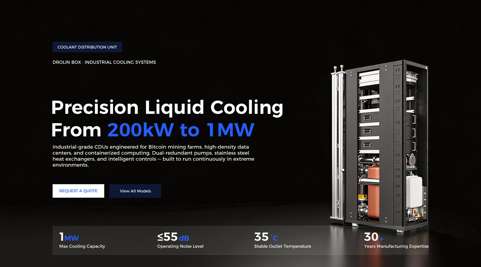
The DroLin CDU range covers five capacity points: 200kW, 400kW, 600kW, 800kW, and 1,000kW (1MW). Additionally, a 100kW rack-mounted unit is available to handle smaller deployments. Because each capacity point corresponds to a specific ASIC deployment range, choosing correctly is vital to avoid two common operator mistakes. On one hand, undersizing produces thermal throttling, reduced hashrate, and a shortened ASIC lifespan. On the other hand, oversizing wastes upfront capital and reduces partial-load operating efficiency.
Fortunately, the sizing calculation is direct. First, add up the total installed ASIC power draw in watts. Next, multiply that sum by 1.15–1.20 to account for overclocking headroom and environmental derating. That final number represents your minimum CDU cooling capacity at a 25°C ambient. Crucially, all DroLin CDU capacity ratings use a 25°C facility-side inlet water temperature as the baseline reference point. This detail matters because as facility water inlet temperature rises, effective CDU cooling capacity drops. For instance, at 35°C facility inlet water, a 1MW-rated CDU delivers approximately 850–900kW of effective cooling.
Deployment mapping at 25°C ambient:
| CDU Model | Cooling Capacity | Typical ASIC Load | Container Configuration |
| 200kW | 200kW | 36–38 × S21 Hydro | Small farm / colo rack |
| 400kW | 400kW | 72–75 × S21 Hydro | Half-container farm |
| 600kW | 600kW | 110–115 × S21 Hydro | Large containerized block |
| 800kW | 800kW | 145–150 × S21 Hydro | Multi-container farm block |
| 1MW | 1,000 kW | 185–190 × S21 Hydro | Full 40HC stack deployment |
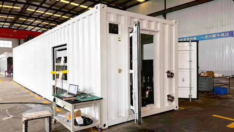
To mistake-proof high-density deployments, let’s look at a practical application. For the stacked 40HC liquid cooling container—specifically DroLin’s 420-unit S21/S19 configuration operating at approximately 2,250kW of total installed power—the correct approach utilizes two parallel 1MW units running in load-sharing mode, complemented by a third 1MW unit on active standby.
By employing this 2N+1 architecture, the system ensures full, uncompromising redundancy even at maximum thermal load. In practice, either active CDU is robust enough to absorb 100% of the cooling load independently. Furthermore, should a fault occur, the standby unit immediately covers either active unit’s failure through a seamless, automatic transfer.
Pro-Tip:
Never size a CDU to run at 100% rated capacity under normal operating conditions. Design for 75–80% utilization at peak load. The remaining headroom absorbs ambient temperature spikes during summer months, compensates for partial coolant chemistry degradation between maintenance cycles, and provides the thermal buffer that prevents a sudden hashrate increase (from network difficulty drop, for example) from immediately pushing the cooling system into saturation.
One parameter operators frequently underweight in CDU selection is outlet temperature stability — specifically, the ±1°C specification. This is not an aesthetic metric. Antminer S21 Hydro firmware monitors inlet coolant temperature and adjusts fan speed and frequency accordingly. Coolant temperature oscillations of ±3–5°C produce corresponding hashrate oscillations as the miner’s thermal management algorithm chases a moving target. Over a 30-day period, this instability measurably reduces average effective hashrate per machine compared to stable ±1°C inlet conditions. The PLC-controlled flow regulation in the DroLin CDU maintains outlet temperature within ±1°C by continuously adjusting secondary loop pump speed via variable frequency drive in response to the return temperature sensor — a closed-loop control that eliminates the hunting behavior common in simpler on/off controlled systems.
PLC Control Architecture and Operational Intelligence
Rather than acting as a simple thermostat, the control system in a modern CDU functions instead as a highly sophisticated, multi-variable process controller. To maintain peak stability, it continuously monitors at minimum six continuous inputs: secondary loop outlet temperature, secondary loop return temperature, primary loop inlet temperature, secondary loop pressure, primary loop pressure, and secondary loop flow rate. By constantly leveraging this comprehensive sensor array, the system successfully ensures perfectly stable operating conditions, even across widely varying load profiles.
The DroLin CDU's PLC-based control system executes the following core logic continuously during operation
Temperature regulation:
Secondary loop outlet temperature setpoint is operator-configurable (default 35°C for Antminer S21 Hydro compatibility). The PLC reads the outlet temperature sensor at 1-second intervals and adjusts secondary pump variable frequency drive output to modulate flow rate. Higher flow rate → shorter coolant residence time in the heat exchanger → warmer outlet temperature (counter-intuitive but correct: at high flow, less heat transfer per unit volume occurs). Lower flow rate → longer residence time → cooler outlet. This inverse relationship means the PLC must be tuned with appropriate integral and derivative terms to prevent oscillation during load transients.
Pressure management:
Low pressure on the secondary loop’s inlet side indicates potential for pump cavitation or circuit leakage. The PLC monitors pressure continuously and triggers an alarm at preset thresholds — typically 0.5 bar above the minimum no-cavitation pressure for the installed pump model. High differential pressure across the filter element indicates increasing filter loading and triggers a filter replacement alert before flow restriction becomes severe enough to affect CDU capacity.
Pump rotation and health monitoring:
In standby-redundancy configurations, the PLC alternates the active pump on a configurable schedule—typically every 168 hours (one week)—specifically to equalize bearing wear across both units. To support this lifecycle management, each pump’s runtime hours, start count, and pressure performance curve are continuously logged and made accessible via the remote monitoring interface. In turn, any deviation from baseline performance curves—such as a pump requiring a higher frequency drive output to maintain target flow—acts as an early warning sign. This metrics shift indicates bearing wear progression, thereby predicting maintenance requirements 200–400 hours in advance.
Remote monitoring:
The PLC exposes all sensor data and operational parameters via Modbus TCP/IP, enabling integration with site SCADA systems, mining farm management platforms, or simple SNMP-based monitoring dashboards. Critical alarm states — pump failure, high outlet temperature, low flow, filter replacement required — can be configured for immediate notification via email or SMS relay. For operators managing multiple containerized farms across geographically distributed sites, this remote visibility eliminates the need for on-site personnel to detect cooling system anomalies before they progress to hardware impact.
Pro-Tip:
When integrating a DroLin CDU into a mining management platform, map the secondary loop outlet temperature sensor to your ASIC monitoring dashboard. Set a correlating alert: if CDU outlet temperature exceeds 37°C AND average ASIC inlet temperature rises above 38°C simultaneously, the root cause is almost certainly either reduced CDU cooling capacity (check pump status and filter differential pressure) rather than a miner-level issue. This two-variable correlation halves diagnostic time during thermal incidents.
Closing Technical Summary
The CDU market reached $2.54 billion in 2026. That number has nothing to do with marketing cycles. Modern high-density computing — whether AI accelerators, HPC nodes, or next-generation ASIC miners — produces heat loads that air-based systems cannot dissipate at acceptable PUE values. The CDU is the engineering response to that physical constraint.
Its internal architecture determines outcomes. Pump redundancy topology, heat exchanger material selection, filtration design, and control system capability decide whether a liquid-cooled mining farm runs as a reliable revenue asset or a continuous maintenance liability.
When evaluating CDU systems, operators should look beyond single-dimension metrics like kW capacity or unit price per kilowatt. A robust evaluation framework must examine pump transfer time and failure detection logic, while also accounting for heat exchanger material compatibility with local water chemistry. Furthermore, it should ensure filters can be serviced under live operation and confirm seamless control system integration.
These parameters answer one question. When a pump seal fails at 3AM, does this CDU handle it automatically — or do you need to manually intervene before your miners start throttling?