






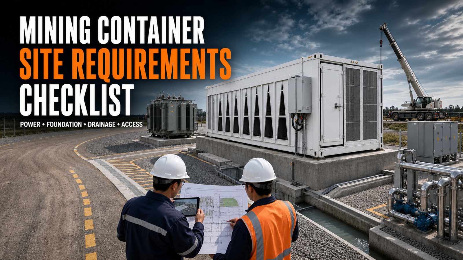

A flat plot and a nearby power line do not make a mining site deployable.
The real test is whether the site can receive a loaded container, place it safely, energize it without overloading the electrical system, reject heat on the hottest design day, drain stormwater, support maintenance access and preserve an emergency route.
Miss one of those conditions and a “plug-and-play” container becomes a civil works project after delivery.
That is why mining container site requirements should be confirmed before the final quotation, not after the equipment reaches the gate. Site information changes the transformer size, container quantity, cooling configuration, cable route, foundation design, installation method and project cost.
Design the site before ordering the box.
1. Site Readiness Starts with the Actual Miner List
The first step in mining farm site preparation is not measuring the land. It is defining the IT load.
Prepare the following information:
Miner brand and exact model
Quantity of each model
Rated and maximum input power
Required input voltage
Air-cooled or hydro-cooled configuration
Planned overclocking or high-energy operating mode
Initial deployment load and future expansion load
Do not calculate the project from nominal container capacity alone. Two containers with the same physical dimensions can have very different electrical and cooling requirements when one carries 3.5kW air-cooled miners and the other carries 5kW-class hydro miners.
Use this basic load formula:
IT Load (kW) = Miner Quantity × Maximum Miner Input Power (kW)
Facility demand must then include the cooling equipment, pumps, fans, controls, lighting, network equipment and distribution losses.
If PUE is being used:
Facility Load (kW) = IT Load × Design PUE
Do not add the cooling load again if it is already included in the PUE model.
Illustrative Transformer Calculation
Assume a project has:
300 miners
3.5kW maximum input per miner
1,050kW IT load
1.10 modeled PUE
0.95 power factor
80% planned transformer loading
The calculation becomes:
Facility Load = 1,050 × 1.10 = 1,155kW
Operating kVA = 1,155 ÷ 0.95 = 1,216kVA
Required Nameplate Capacity = 1,216 ÷ 0.80 = 1,520kVA
The project would then move to the next appropriate standard transformer size, subject to local standards, ambient temperature, altitude, harmonic studies, fault-current analysis and the selected redundancy strategy.
This is an example, not a universal transformer recommendation.
Pro Tip
For a 3MW to 5MW mining farm, evaluate modular electrical blocks instead of connecting every container to one oversized distribution point. Separate transformer and switchgear blocks can simplify staged commissioning, maintenance and fault isolation.
2. Confirm the Utility Supply Before Selecting the Transformer
A utility saying that power is “available nearby” is not enough. Buyers need to confirm what can actually be delivered at the site boundary.
The electrical survey should identify:
Confirmed utility capacity
Grid connection date
Supply voltage and frequency
Available short-circuit current
Transformer ownership boundary
Metering requirements
Grounding method
Protection coordination requirements
Maximum demand restrictions
Expansion capacity
Generator or backup-power requirements
Transformer sizing is not simply IT load plus a fixed percentage. The engineer must consider power factor, continuous loading, harmonic content, ambient temperature, altitude, future expansion and the consequences of losing one transformer.
High altitude deserves particular attention. Lower air density reduces the cooling performance of air-cooled electrical equipment. Schneider Electric, for example, publishes an altitude derating method for certain low-voltage dry-type transformers above 1,000 meters. That does not apply automatically to every transformer, but it demonstrates why the supplier’s altitude curve must be checked.
The same issue affects miners. BITMAIN lists an operating altitude of up to 2,000 meters for the S21 and states that, between 900 and 2,000 meters, its maximum operating temperature decreases as altitude increases.
The practical decision is clear: altitude belongs in the RFQ.
3. Temperature, Humidity and Altitude Change the Cooling Design
“Average annual temperature” is not a useful design value on its own.
The cooling system must be evaluated against:
Maximum dry-bulb temperature
Maximum wet-bulb temperature
Daily temperature range
Seasonal minimum temperature
Relative humidity
Dew point
Dust and sand exposure
Rain and snow
Salt spray or corrosive air
Prevailing wind direction
Site altitude
For reference, BITMAIN specifies an operating temperature of 0°C to 45°C and non-condensing relative humidity of 10% to 90% for the S21. Other miner models have different limits.
A site reaching 43°C may appear to remain within that range. However, the container still needs enough temperature margin to account for intake restriction, dirty filters, hot-air recirculation and uneven airflow.
Design for the dirty filter and the hottest afternoon.
Humidity creates a different risk. High relative humidity is not automatically a failure condition, but condensation is. Cold pipes, manifolds or coolant connections can fall below the local dew point, causing moisture to form near electrical equipment.
For hydro miners, site preparation must also follow the miner’s coolant requirements. BITMAIN’s published S21 Hyd. specifications, for example, identify:
380V to 415V three-phase input
Mode-dependent inlet-water temperature
8 to 10 L/min water flow per miner
Maximum water pressure of 3.5 bar
Defined working-fluid and water-quality requirements
These values are model-specific. They explain why “192 hydro miners” is not enough information for designing the site pipework.
Cold-Climate Requirements
A liquid-cooled site in a freezing climate may require:
Approved glycol concentration
Freeze-protected outdoor piping
Heat tracing where appropriate
Low-point drains
Insulated valves and manifolds
A controlled shutdown and drain procedure
Dry-cooler controls for low ambient conditions
Air-cooled containers also need cold-weather planning. Snow accumulation, wind-driven snow, icing and excessively cold intake air can interrupt airflow or push equipment outside the recommended operating envelope.
4. The Foundation Must Carry Point Loads, Not Just Total Weight
A mining container is not a uniformly distributed warehouse load.
Its weight is transferred through structural rails, support points or corner castings. A foundation can have enough total bearing capacity and still deform if the support locations are incorrect.
A qualified structural or civil engineer should confirm:
Container operating weight
Shipping weight
Support-point reactions
Soil bearing capacity
Settlement risk
Frost depth
Seismic conditions
Wind and uplift loads
Equipment vibration
Local concrete and reinforcement standards
Required anchoring method
Finished elevation and levelness tolerance
Common foundation arrangements include:
A continuous reinforced concrete slab
Reinforced grade beams
Isolated concrete piers
Corner foundations connected by structural beams
The correct option depends on the container structure, soil report and local climate. A universal slab thickness should not be copied from another project.
The pad should also provide enough space for:
Door opening
Electrical-panel access
Filter replacement
Fan maintenance
Pipe and valve service
Emergency egress
Safe removal of miners or pumps
In the United States, OSHA requires sufficient access and working space around electrical equipment. For certain equipment operating at 600V or less, the standard also requires working-space width of at least 762mm or the equipment width, whichever is greater, and enough clearance for doors to open at least 90 degrees. Other countries have their own requirements.
Do not use this U.S. value as a global layout rule. Use it as a reminder that electrical service space cannot become storage space.
Pro Tip
Ask the container supplier for a foundation-interface drawing before pouring concrete. The drawing should show the footprint, support points, operating weight, cable-entry locations, pipe interfaces, door swings and maintenance zones.
5. Drainage Is Part of Electrical Reliability
The finished pad should not sit at the lowest point of the site.
Surface grading should move rainwater away from:
Container doors
Electrical cabinets
Transformer pads
Cable trenches
CDU foundations
Pump stations
Dry-cooler supports
The site drainage plan should address:
Finished pad elevation
Surface slope
Trench drains
Culverts and runoff channels
Extreme rainfall events
Snowmelt
Erosion control
Sediment control
Coolant spill containment
Separation between stormwater and process drainage
Standing water around underground cables, grounding connections and equipment foundations creates maintenance and safety problems. It can also restrict service vehicles after heavy rain.
For U.S. projects, industrial stormwater or construction-related runoff may be subject to federal, state or local permitting requirements. EPA guidance notes that runoff can collect pollutants from exposed industrial activities and that many permitting programs are administered by individual states.
The correct drainage design is therefore both an engineering decision and a permitting decision.
6. Preserve Fire Access and Emergency Isolation
A dense site layout may improve land utilization while making emergency response almost impossible.
Before freezing the mining container site layout, confirm:
Fire-engine access
Emergency vehicle turning space
Container separation requirements
Access to electrical disconnects
Emergency shutdown locations
Personnel escape routes
Combustible-material controls
Fire-water or extinguishing-system requirements
Transformer separation and containment
Local noise and boundary restrictions
The local fire authority or Authority Having Jurisdiction should approve the applicable clearances and emergency-access plan.
Do not route permanent pipes, temporary cables or parked vehicles through the fire lane. A clear route on the drawing is useless if it is blocked during operation.
7. Survey the Entire Delivery Route
The delivery route does not begin at the project gate. It begins at the port, depot or regional highway connection.
A route survey should verify:
Legal vehicle and loaded-container dimensions
Axle and gross-weight limits
Oversize or overweight permit requirements
Bridge and culvert capacity
Road surface strength
Gate width
Vertical clearance
Overhead power and communication lines
Railway crossings
Road gradients
Tight intersections
Switchbacks
Tractor-trailer swept path
Seasonal road restrictions
Space for reversing and staging
Do not approve access based on road width alone. A long tractor-trailer may enter a straight gate and still fail at the final 90-degree turn.
In the United States, truck size and weight rules vary by state, and oversize or overweight movements may require state-issued permits. The FHWA compilation also emphasizes dimensions, axle loads and route-specific restrictions.
For overseas projects, the same principle applies: verify every jurisdiction between the arrival port and the foundation.
Go standard where possible. Survey everything anyway.
8. Plan the Crane Lift Before the Container Arrives
The crane contractor needs more than the container’s total weight.
The lift plan should include:
Certified lifting weight
Center of gravity
Lifting points
Rigging method
Crane radius
Boom configuration
Wind limits
Ground-bearing pressure
Outrigger locations
Outrigger-mat design
Exclusion zone
Spotter and communication method
Overhead-utility clearance
Final orientation on the pad
Crane capacity decreases as working radius increases. A crane that can lift the container close to its chassis may not have enough capacity when forced to stand farther away because the pad is inaccessible.
Overhead power lines are a critical constraint. Under U.S. OSHA construction rules, if the crane, load line or load could approach within 20 feet of a power line, the employer must follow the required de-energization, 20-foot-clearance or voltage-based Table A procedure.
Local lifting rules may differ, but the planning lesson is universal: find the power lines before booking the crane.
Pro Tip
Send the crane contractor the final site plan, container weight, lifting-point drawing and delivery-truck dimensions. A phone message saying “one 40ft container” is not a lift plan.
9. Air-Cooled and Liquid-Cooled Sites Need Different Space
The mining container foundation may look similar, but the surrounding infrastructure does not.
| Site Requirement | Air-Cooled Container | Liquid-Cooled Container |
|---|---|---|
| Primary heat path | Outdoor air through miners | Coolant loop to CDU and heat rejection |
| Critical external space | Unobstructed intake and exhaust | CDU, pumps, pipework and dry cooler |
| Main climate risk | Dust, heat, snow and recirculation | Freezing, water quality and approach temperature |
| Major interfaces | Power, network, intake and exhaust | Power, network, supply and return pipes |
| Maintenance priority | Filters, fans and miner cleaning | Pumps, strainers, valves and coolant quality |
| Layout risk | Exhaust entering another intake | Excessive pipe length or poor hydraulic balance |
| External equipment | Transformers and switchgear | Transformers, switchgear, CDU and dry cooler |
Air-Cooled Mining Container Site Preparation
An air-cooled container needs a controlled path for intake and exhaust air.
Check:
Prevailing wind direction
Distance from walls and adjacent containers
Hot-air recirculation risk
Dust-screen access
Filter-removal space
Exhaust-noise direction
Snow or vegetation blockage
Space for fan maintenance
Placing two containers close together may improve density while allowing one container’s exhaust to enter the next container’s intake.
That is not density. It is recycled heat.
Liquid-Cooled Mining Container Site Preparation
A liquid-cooled system needs space for the entire heat-rejection chain:
Miner → Internal Manifold → CDU → External Loop → Dry Cooler
Confirm:
CDU location
Dry-cooler foundation
Supply and return pipe route
Pipe diameter and material
Design flow and pressure
Flange or coupling standard
Expansion tank
Air vents
Low-point drains
Strainers and water treatment
Pump electrical supply
Freeze protection
Leak detection
Service access around valves and heat exchangers
A short container quotation can hide a large site-side piping scope. Define the battery limits before comparing prices.
10. Freeze Every Interface Before Manufacturing
Many commissioning delays come from small interface mismatches:
The site supplies 480V, but the equipment requires another voltage.
The cable is too large for the selected gland plate.
The PDU outlets do not match the miner power cords.
The supply and return pipes are reversed.
The flange standards are different.
The control system has no agreed communication protocol.
The network cabinet has no fiber termination point.
The concrete is poured before the underground cable route is confirmed.
Prepare an interface schedule covering:
Electrical Interfaces
Utility voltage and frequency
Transformer secondary voltage
Main switchgear rating
PDU quantity and rating
Cable size and conductor material
Cable-entry direction
Gland-plate dimensions
Grounding and bonding
Emergency-stop circuit
Auxiliary power
Short-circuit rating
Protection settings
Liquid-Cooling Interfaces
Supply and return temperature
Design flow
Maximum pressure
Pipe diameter
Pipe material
Flange or coupling standard
Working fluid
Water-quality requirement
Fill and drain connection
Air vent
Expansion control
Leak detection
CDU and dry-cooler control signals
Communication Interfaces
Fiber or Ethernet entry
Network cabinet location
IP-address plan
PLC protocol
Remote-monitoring platform
Alarm contacts
Environmental sensors
Access-control requirements
One signed interface schedule can prevent weeks of site rework.
11. Mining Container Site Requirements Checklist
Use this checklist before approving the final quotation.
Project Information
Project country and exact location
Site coordinates
Miner models and quantities
Initial and future IT load
Required commissioning date
Electrical System
Utility capacity confirmed in writing
Supply voltage and frequency confirmed
Transformer sizing completed
Ambient and altitude derating checked
Short-circuit and protection study planned
Switchgear and PDU interfaces confirmed
Cable route and cable-entry points confirmed
Grounding design completed
Climate and Cooling
Maximum and minimum temperatures
Relative humidity and dew point
Altitude
Dust, sand, snow or salt exposure
Prevailing wind direction
Air intake and exhaust zones confirmed
CDU and dry-cooler locations confirmed
Freeze-protection method selected
Coolant and water-quality requirements confirmed
Civil Works
Geotechnical information available
Foundation design approved
Container support points confirmed
Anchoring design confirmed
Finished elevation established
Drainage and runoff route completed
Cable trenches and pipe sleeves coordinated
Maintenance clearances preserved
Logistics and Installation
Port-to-site route surveyed
Gate width and height checked
Bridge and culvert capacity checked
Final turning path simulated
Delivery staging area available
Crane position approved
Ground-bearing pressure checked
Overhead power lines identified
Fire and emergency access preserved
Common Site-Preparation Mistakes
The most expensive site mistakes are usually predictable:
Ordering the transformer from average miner power rather than maximum project demand.
Pouring the foundation before receiving the equipment-interface drawing.
Using annual average temperature instead of the hottest design condition.
Ignoring altitude derating.
Measuring the gate but not simulating the tractor-trailer turn.
Booking a crane without checking working radius and ground capacity.
Placing air-cooled containers where exhaust can return to the intake.
Locating a dry cooler without space for pipework and maintenance.
Treating stormwater drainage as landscaping.
Allowing cables, pipes or equipment to block the emergency route.
Each mistake is cheaper to fix on a drawing than on an operating site.
What to Send DroLinBox Before Site Planning
To receive a preliminary mining-container configuration and site-planning review, send:
Project country and location
Available power capacity
Miner model and quantity
Maximum site temperature
Minimum site temperature
Site altitude
Preferred cooling method
Target deployment date
Site photographs
Site plan, satellite image or available layout drawing
If available, also provide the utility single-line diagram, transformer information, road-access photographs and the distance between the planned container area and the electrical connection point.
Use the Mining Container Quote Checklist to prepare your commercial and technical inputs.
Review the Mining Container Installation Checklist before delivery and commissioning.
Learn more about Mining Farm Site Planning Services or contact DroLinBox to submit your project information.
Final Verdict: A Deployable Site Is More Valuable Than an Empty Megawatt
The best mining container cannot correct a weak grid connection, an undersized transformer, an uneven foundation or a delivery route that the truck cannot enter.
Good mining farm site preparation connects every project boundary before manufacturing begins:
Power → Container → Cooling → Foundation → Logistics → Commissioning
Confirm those interfaces early and the container can arrive as a modular infrastructure asset.
Ignore them and the site will spend its deployment budget solving avoidable problems.
Prepare the site first. Then price the container.
FAQ
What foundation does a mining container require?
The foundation may use a reinforced slab, grade beams or isolated piers, depending on the container support points, operating weight, soil bearing capacity, frost depth, wind and seismic conditions. A structural engineer should design it from the supplier’s foundation-interface drawing.
How much transformer capacity does a mining container need?
Calculate the maximum miner IT load first, then include cooling and auxiliary loads through a facility-load or PUE model. Convert kW to kVA using the expected power factor and include the selected loading target, ambient conditions, altitude and redundancy requirements.
Can a mining container be installed directly on compacted gravel?
Some temporary configurations may use engineered supports, but ordinary compacted gravel should not be assumed to provide adequate levelness, settlement control, anchoring or drainage. The supplier and local civil engineer should approve the support method.
How much space is required around a mining container?
There is no universal clearance. Space depends on door swings, electrical working clearances, airflow, exhaust recirculation, filter replacement, pipe maintenance, fire access and local regulations. The final layout should use the supplier’s maintenance zones and the local code requirements.
What information is needed before requesting a site layout?
Provide the project location, miner models, quantities, available power, voltage, climate data, altitude, cooling preference, site photographs, road-access information and an available site plan.