







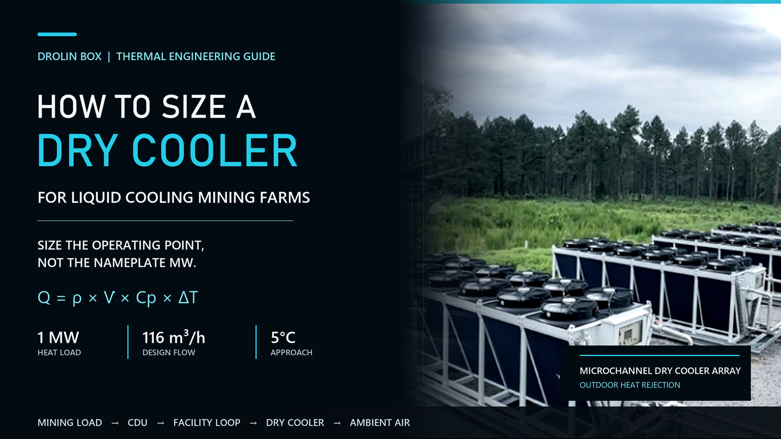

A 1MW mining farm can still overwhelm a dry cooler labeled “1MW.”
The label may be technically correct at a 25°C ambient temperature, a generous fluid temperature, clean coils, full fan speed and pure water. Move that same unit to a 40°C mining site, demand colder coolant, add glycol and allow dust to build on the coil, and its available heat rejection can fall well below the catalog number.
That is the real dry cooler sizing problem.
Do not buy a dry cooler by matching its nominal megawatt rating to the mining farm’s electrical capacity. Size the entire thermal chain:
ASIC heat load → Technology cooling loop → CDU → Facility loop → Dry cooler → Outdoor air
Every arrow represents a temperature, flow, pressure or capacity limit. If one component is selected under a different operating condition, the whole liquid cooling system may lose capacity on the hottest day of the year.
1. The Nameplate Capacity Trap
A dry cooler does not have one fixed cooling capacity.
Its available capacity changes with:
Temperatura del bulbo seco exterior
Fluid entering temperature
Required fluid leaving temperature
Fluid flow rate
Water or glycol concentration
Airflow through the coil
Fan speed
Site altitude
Coil fouling
Air recirculation
Number of operating fans
Therefore, a quotation stating only “1MW dry cooler” is incomplete.
A technically useful selection should read more like this:
The dry cooler rejects 1,080kW at 35°C outdoor dry-bulb temperature, cooling the specified fluid from 48°C to 40°C at the calculated flow rate and selected fan operating condition.
Without those conditions, two suppliers can both quote a 1MW system while offering very different real-world performance.
Buy the operating point, not the megawatt label.
2. Start with the Heat Entering the Liquid Loop
Dry cooler sizing should begin with the maximum heat that must be transferred into the outdoor air.
The first calculation is the ASIC IT load:
IT Load (kW) = Miner Quantity × Maximum Miner Input Power (kW)
If several miner models are used:
IT Load = Sum of Each Miner Quantity × Its Maximum Input Power
Use the maximum continuous input power expected under the selected operating mode. Do not calculate from average power if the miners may operate in high-performance or overclocked modes.
Next, determine how much of that load actually enters the liquid loop.
For a fully hydro-cooled miner, most of the miner heat may be captured by the coolant. However, power supplies, electrical cabinets, network devices and auxiliary equipment may still release some heat into the air.
A preliminary model can be written as:
Liquid Heat Load = IT Load × Confirmed Liquid Capture Ratio + Heat Added to the Loop by Pumps and Other Equipment
The design duty is then:
Design Heat Rejection = Liquid Heat Load × Design Factor
The design factor should cover named uncertainties such as future expansion, operating variation, heat-exchanger performance, fouling and measurement tolerance. It should not be an arbitrary percentage added to every project.
Pro Tip
Ask the miner and CDU suppliers to confirm the heat entering each cooling loop. “1MW electrical load” and “1MW liquid heat load” are often treated as identical during sales discussions, but they may not be identical at the equipment boundary.
3. IT Load Facility Power and Heat Rejection Are Different Numbers
These three values are related, but they should not be used interchangeably.
IT Load
This is the electrical power consumed by the miners and associated IT equipment.
Facility Power
This includes IT power plus pumps, fans, controls, lighting, network equipment, ventilation and electrical losses.
When PUE is used:
Facility Power = IT Load × PUE
For example:
IT load: 1,000kW
Design PUE: 1.08
Total facility demand: 1,080kW
However, that does not automatically mean the dry cooler must reject exactly 1,080kW.
Some facility losses may be released outside the liquid loop. Transformer losses, cabinet heat and ventilation loads may be rejected separately. At the same time, pump energy that enters the coolant can increase the liquid heat-rejection requirement.
The thermal balance should identify where each kilowatt becomes heat.
Do not size the dry cooler directly from the utility meter.
4. The CDU and Dry Cooler Must Be Rated at the Same Conditions
The CDU is the thermal and hydraulic bridge between the miner cooling loop and the facility heat-rejection loop.
A liquid-to-liquid CDU normally performs four jobs:
Transfers heat through a heat exchanger
Circulates coolant through the technology loop
Controls supply temperature
Maintains the required flow and pressure
A CDU advertised as 1MW does not necessarily transfer 1MW under every temperature condition.
Its capacity depends on:
Primary-loop supply and return temperatures
Secondary-loop supply and return temperatures
Flow rate on both sides
Heat-exchanger effectiveness
Fluid properties
Pressure drop
Pump operating point
If the dry cooler returns warmer fluid than expected, the temperature difference across the CDU heat exchanger becomes smaller. The CDU may then be unable to maintain the required coolant supply temperature even though its nominal rating matches the IT load.
This creates a common engineering mismatch:
Dry cooler selected at 25°C ambient
CDU rated using colder facility water
Project site reaches 40°C
Actual facility-water temperature rises
CDU heat-transfer capacity falls
Miner inlet temperature exceeds the target
The dry cooler and CDU must therefore be selected as one connected system.
5. Understand Range and Approach Temperature
Two temperatures control much of the dry cooler capacity calculation: range y approach.
Fluid Range
The range is the temperature difference between the hot fluid entering the dry cooler and the cooled fluid leaving it.
Range = Dry Cooler Entering Fluid Temperature − Leaving Fluid Temperature
Example:
Entering fluid: 48°C
Leaving fluid: 40°C
Range: 8°C
A wider range reduces the flow required for the same heat load. However, the CDU and miners must accept the corresponding temperatures.
Approach Temperature
For a dry cooler, approach is commonly defined as the difference between the cooled fluid leaving the dry cooler and the outdoor entering-air dry-bulb temperature.
Approach = Leaving Fluid Temperature − Outdoor Dry-Bulb Temperature
Example:
Outdoor dry bulb: 35°C
Dry cooler leaving fluid: 40°C
Approach: 5°C
A smaller approach is harder and more expensive to achieve. It normally requires more coil surface, more airflow, higher fan power or a larger physical footprint.
A dry cooler operating in dry mode cannot produce leaving fluid below the outdoor dry-bulb temperature. Adiabatic assistance may temporarily improve performance by pre-cooling the entering air, but it introduces water use, water-quality requirements and additional maintenance.
Pro Tip
Do not write “5°C approach” in an RFQ without defining the two temperatures used. Suppliers sometimes use different temperature references. State the outdoor design dry bulb and required dry cooler leaving-fluid temperature separately.
6. Ambient Temperature Can Remove Capacity When You Need It Most
Dry cooler performance should be evaluated at the project site’s design summer condition.
The site survey should include:
Maximum design dry-bulb temperature
Daily temperature range
Duration of high-temperature periods
Altitude
Solar exposure
Dust and sand
Prevailing wind
Space between multiple dry coolers
Nearby walls or containers
Hot-air recirculation risk
Selecting a unit from annual average temperature is a serious mistake.
A mining site may have an annual average of 22°C while still experiencing several weeks above 38°C. Those weeks determine whether the farm can remain at full hashrate.
Altitude also matters. Lower air density reduces the mass of air moved through the coil for a given volumetric airflow. The manufacturer should apply the appropriate altitude correction to the coil and fan selection.
Layout can create another hidden derating factor. If hot discharge air returns to the dry cooler intake, the unit may experience a much higher entering-air temperature than the weather station reports.
Design for the air entering the coil, not the temperature shown on a phone.
7. Calculate the Required Dry Cooler Flow Rate
The basic heat-transfer relationship is:
Q = ρ × V̇ × Cp × ΔT
Where:
Q = Heat load in kW
ρ = Fluid density in kg/m³
V̇ = Volumetric flow in m³/s
Cp = Specific heat capacity in kJ/kg·K
ΔT = Fluid temperature difference in K or °C
For water near typical mining-farm operating temperatures, a useful preliminary formula is:
Flow (m³/h) ≈ Q (kW) ÷ [1.163 × ΔT (°C)]
Preliminary Water-Flow Examples for a 1MW Heat Load
| Fluid Range | Approximate Flow |
|---|---|
| 5°C | 172m³/h |
| 8°C | 107m³/h |
| 10°C | 86m³/h |
These figures apply to water as a preliminary calculation.
If glycol is used, the density, specific heat and viscosity change. A glycol mixture may require a different flow rate, produce a higher pressure drop and reduce coil heat-transfer performance.
The final dry cooler selection must use the actual fluid and concentration.
8. Flow Rate Does Not Select the Pump by Itself
A pump must deliver the required flow at the total system pressure drop.
For a closed cooling loop, operating pump head mainly covers:
Straight-pipe friction
Elbows and fittings
Valves
Filters and strainers
Dry cooler coil pressure drop
CDU heat-exchanger pressure drop
Manifolds
Flow-control devices
Available fouling allowance
The total vertical height should not simply be added as continuous static head in a completely closed loop because the rising and falling fluid columns largely balance during operation. Elevation still affects filling, system pressure, expansion control and component pressure ratings.
Pipe diameter directly changes the pump requirement.
A smaller pipe may reduce initial material cost, but it increases velocity, friction loss and pump energy. A larger pipe reduces pressure drop but increases pipe cost, coolant volume, insulation and installation space.
The correct diameter balances:
Acceptable fluid velocity
Friction loss
Pump efficiency
Noise and vibration
Erosion risk
Valve and fitting cost
Future expansion
Coolant viscosity at the minimum site temperature
Pro Tip
Request a complete system curve instead of accepting a pump selected only by maximum flow. The operating point must remain within an efficient region of the pump curve with clean filters, dirty filters and the planned valve positions.
9. Fan Quantity Is Not the Same as Fan Redundancy
Dry coolers often use several axial fans, but a high fan count does not automatically create an N+1 system.
If one fan stops:
Airflow may become uneven across the coil
Capacity loss may be greater than the failed fan’s percentage
Adjacent fans may pull air through the inactive fan opening
Remaining fans may need to operate at higher speed
Noise and fan energy may increase
The dry cooler may no longer meet full load at design ambient
Ask the supplier to provide performance for:
All fans operating
One fan unavailable
Reduced fan speed
Maximum design ambient
Actual glycol concentration
Expected coil fouling condition
EC fans or variable-frequency control can reduce power consumption during cooler weather and part-load operation. They also allow staged control, but controls do not replace physical heat-transfer capacity.
Fan redundancy protects airflow. It does not automatically protect the coil, pump, controller or power supply.
10. N+1 and Modular Deployment Logic
N+1 means the system can meet the required design load after one defined module becomes unavailable.
The failure unit must be clearly identified.
It could mean:
One fan
One pump
One CDU
One dry cooler module
One electrical feeder
One complete cooling block
These are not equivalent.
For a modular mining farm, a practical architecture may pair each mining-container group with a CDU and dry cooler block. Additional blocks can then be added as the project expands.
This approach offers several advantages:
Staged CAPEX
Easier commissioning
Smaller failure zones
Maintenance without shutting down the entire site
Clearer matching between mining load and cooling capacity
Simpler future expansion
For true N+1 protection, the remaining modules must reject the full design heat load at the maximum design ambient temperature.
Pro Tip
Do not accept “N+1 fans” as proof that the cooling system is N+1. Ask what happens if an entire dry cooler circuit, CDU controller, pump skid or power feeder becomes unavailable.
11. A Practical 1MW Dry Cooler and CDU Sizing Example
Consider a preliminary 1MW liquid cooling mining farm.
Project Inputs
Maximum IT load: 1,000kW
Preliminary design heat rejection: 1,080kW
Outdoor design dry bulb: 35°C
Dry cooler entering fluid: 48°C
Dry cooler leaving fluid: 40°C
Fluid range: 8°C
Approach temperature: 5°C
Facility-loop fluid: Water
Site expansion: Not included
The 1,080kW value is an example that includes confirmed loop heat and an engineering allowance. It is not a universal multiplier for every 1MW project.
Step 1: Calculate the Facility-Loop Flow
Flow = 1,080 ÷ (1.163 × 8)
Flow ≈ 116m³/h
The preliminary facility-loop flow is therefore approximately 116m³/h.
Step 2: Select the CDU
The CDU must transfer at least 1,080kW at the specified primary- and secondary-loop temperatures.
The CDU selection must also confirm:
Primary-side flow and pressure drop
Secondary-side flow and pressure drop
Miner supply-temperature setpoint
Heat-exchanger performance
Pump curve
Filtration
Expansion control
Leak detection
Water-quality requirements
Pump and control redundancy
A CDU with a catalog rating above 1,080kW may still be unsuitable if that rating was measured with colder facility water or a larger temperature difference.
Step 3: Select the Dry Cooler
The dry cooler bank must reject at least 1,080kW under all specified conditions:
35°C entering dry-bulb temperature
48°C entering fluid
40°C leaving fluid
Approximately 116m³/h water flow
Project altitude
Selected fan speed
Required sound limit
Defined fouling condition
If glycol is required for freeze protection, the manufacturer must rerun the selection.
Step 4: Choose the Redundancy Strategy
CAPEX-focused configuration
One CDU and one dry cooler bank serve the entire load. This has the lowest equipment cost, but maintenance or a major failure can require project derating or shutdown.
Modular derating configuration
Two cooling blocks share the load. If one block stops, the farm intentionally reduces the operating miner count. This is not full N+1, but it limits the outage area.
Full N+1 configuration
Use enough CDU and dry cooler modules so the remaining modules can transfer and reject the full 1,080kW after one module fails.
For example, three equal modules would each need to provide at least 540kW at the stated operating conditions because any two modules must carry 1,080kW.
Commercial module sizes, hydraulic balancing and control logic must be verified during final selection.
12. What Happens When the Dry Cooler Is Too Small?
An undersized dry cooler rarely fails with one dramatic event. The problem usually develops as a thermal chain reaction.
Outdoor temperature rises.
Dry cooler leaving-fluid temperature increases.
Warmer fluid reaches the CDU.
CDU temperature difference decreases.
Secondary coolant supply temperature rises.
Miner chip temperatures increase.
Miners reduce performance, alarm or shut down.
The project loses hashrate during the most difficult operating hours.
The operational consequences can include:
Thermal derating
Miner shutdowns
Repeated alarms
Higher fan and pump power
Reduced overclocking capability
Thermal cycling
Increased maintenance
Emergency water or chiller rental
Lost mining revenue
Expansion capacity that cannot be used
The cost of insufficient cooling should be included in the ROI model:
Downtime Cost = Offline Miner Quantity × Expected Gross Margin per Miner per Day × Outage Duration
The result changes with cryptocurrency price, network difficulty, miner efficiency and electricity price. That is exactly why thermal capacity should be treated as revenue protection rather than a simple equipment purchase.
13. Dry Cooler RFQ Checklist
Before requesting a dry cooler and CDU quotation, prepare the following information.
Mining Load
Miner brand and exact model
Cantidad de mineros
Maximum power per miner
Carga total de TI
Liquid heat-capture ratio
Planned overclocking
Future expansion load
Site Conditions
Project country and location
Maximum design dry-bulb temperature
Minimum winter temperature
Altitude
Humidity
Dust and sand exposure
Available installation area
Sound restrictions
Air-discharge direction
Thermal Conditions
Required miner coolant supply temperature
Miner return temperature
CDU primary-loop temperatures
CDU secondary-loop temperatures
Dry cooler entering-fluid temperature
Dry cooler leaving-fluid temperature
Required approach
Required fluid range
Hydraulic Conditions
Coolant type
Glycol concentration
Required flow
Pipe length
Pipe material
Estimated fittings and valves
Elevation difference
Filter pressure drop
CDU pressure drop
Dry cooler coil pressure drop
Reliability Requirements
Acceptable miner derating after one failure
Pump redundancy
Redundancia de ventiladores
CDU redundancy
Dry cooler module redundancy
Dual-power requirement
Remote monitoring protocol
Required spare parts
One complete design-condition sheet is more valuable than ten quotations labeled “1MW.”
Final Verdict: Size the Thermal Chain as One System
Dry cooler sizing is not a product-selection exercise. It is a system-balance exercise.
The correct sequence is:
Maximum miner load → Liquid heat load → CDU operating point → Fluid temperatures → Flow rate → System pressure drop → Dry cooler capacity → Redundancy
For a 1MW project, the dry cooler may need more than 1MW of nominal catalog capacity. The actual answer depends on the site ambient temperature, required approach, fluid range, coolant type, CDU performance and failure strategy.
Go modular when uptime and expansion matter.
Use one large cooling block only when the project can accept the maintenance and failure risk.
Most importantly, require every supplier to state capacity at the same operating conditions. That is the only way to compare quotations honestly.
To understand when dry cooling is a better choice than evaporative heat rejection, read Enfriador seco para la refrigeración líquida de centros de datos.
For CDU selection logic, review CDU for AI Data Centers and the DroLinBox CDU Product Page.
For preliminary project sizing, submit your miner model, quantity, project location, power capacity, design temperatures and site layout through the DroLinBox Contact Page.
Preguntas frecuentes
How much dry cooler capacity is required for a 1MW mining farm?
Do not select the dry cooler from the 1MW IT rating alone. Calculate the heat entering the liquid loop, pump heat, design allowance, ambient temperature, fluid temperatures and redundancy requirement. A 1MW IT project may require a dry cooler selection above 1MW at the project’s actual design conditions.
How is dry cooler capacity calculated?
The basic relationship is Q = ρ × V̇ × Cp × ΔT. Final selection also requires the outdoor dry-bulb temperature, approach temperature, fluid type, coil performance, airflow, altitude and fan operating condition.
What flow rate is required for a 1MW dry cooler?
For water, approximately 172m³/h is required at a 5°C range, 107m³/h at an 8°C range and 86m³/h at a 10°C range. Glycol mixtures require recalculation using their actual properties.
Can a dry cooler cool water below ambient temperature?
A standard dry cooler operating in dry mode cannot cool the leaving fluid below the entering-air dry-bulb temperature. Adiabatic assistance or mechanical refrigeration is required when lower temperatures are needed.
Should the dry cooler be larger than the CDU?
Neither component should be selected from nominal capacity alone. The CDU and dry cooler should both meet the project heat load at the same fluid temperatures, flow rates and design ambient condition. Redundancy may require additional installed capacity.